Mixing Valve Controller - Central Heating System Controller
on
Get link
Facebook
X
Pinterest
Email
Other Apps
Over the last few weeks during this winter we were testing performance of the new mixing valve controller in a real world conditions. A working prototype is installed at friends house for a period of three weeks. All working parameters were collected and sent to cloud for monitoring and analysis (via Google Drive). Also device setup can be accessed and parameters can be changed at any time to see how it influence controller performance.
Short video overview of a working controller:
For data monitoring following system have been established:
- Mixing valve controller - DUT (Device Under Test),
- Raspberry Pi computer for exchanging data over UART communication with DUT:
Raspberry Pi is running rclone which uploads all measured data to Google Drive cloud, the same Raspberry downloads configuration file from G Drive which contains working parameters which can be changed. In this way mixing valve controller is fully monitored and controller remotely.
Collected data are stored in .csv file which is plotted for analysis via Plotly Graphing Library for Python.
DUT is installed in a heating circle which supply heat to the apartment of ca 100 m2 living space. Heating circle takes the heat from a buffer tank of 2000 l capacity. Heat is supplied to the buffer tank from pyrolytic solid fuel (wood logs) boiler of 50 kW. This system is presented in the video below:
The analysis of DUT performance
To better understand measured temperatures a basic schematic of the system is given below:
Mixing valve actuator is Seltron AVC05: 3-point, 120s, 5Nm.
Circulating pump is AQART Type 25-6-180, 3 speed.
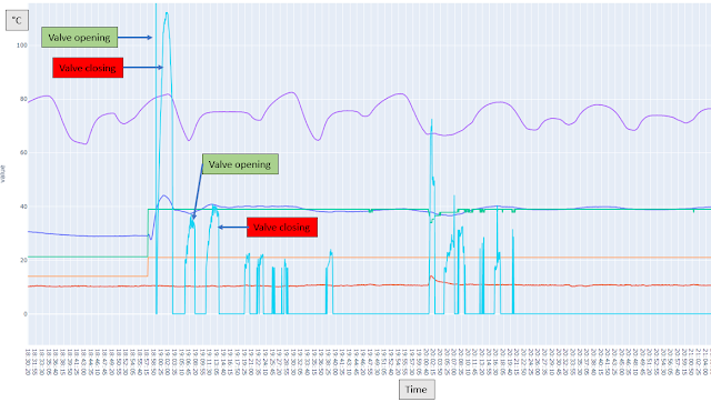
Diagram of one day (24h of 8. February 2022.) of temperature recording is given below.
Buffer tank temperature changes according to heat demand from the building. Oscillations which begin at 17 h is when pyrolytic boiler is fired up. This boiler if fired once per day. Oscillations are due to pump speed modulation as boiler is going through different burning phases. As pump speed change levels of water with different temperature inside tank are being mixed.
Heating controller (DUT) works in a Outside + Room Thermostat mode. This means that signal from room thermostat defines which room temperature is set to be. From diagram it is seen that In Room Temperature (IRT) is changed between 2 values, this is set by a room thermostat. Based on Room Temperature and Outside Temperature (OT) DUT calculate Ongoing Flow Set Temperature(OFST) based on selected heating curve. The PID regulator inside DUT firmware is controlling mixing valve so actual Ongoing Flow Temperature (OFT) is as close as possible to Ongoing Flow Set Temperature.
From the 24h diagram above it is seen that OFT is trying to be close to OFST. It should be noted that when the room thermostat is OFF and lower value IRT is set, the pump is OFF. This pump can be set to and speed between 0 and 100%, but in this case it is set to 0%. This is why mixing valve is unable to control OFT when IRT is low - there is no water circulating.
A detail of DTU operation when IRT is set to low value (room thermostat OFF). The pump stops and OFT first increase, that decrease slowly without DUT and mixing valve control. Control over OFT can be established if pump speed is >0%, but this is not important. The pump is set to 0% to stop the heat delivery because in the case when room thermostat is OFF the heat in not needed.
It is important to see how DUT manages to keep OFT close to OFST during room thermostat ON (heat demand) period. After initial instant change in OFST the OFT takes approx. 20 mins to stabilize. After that, as it an be seen in diagram below, the OFT is kept within 1°C offset from OFST. From diagram it is also seen that OFST is changed (lowered) according to Outside Temperature increase.
The allowed offset of OFT against OFST is defined as DUT working parameter "valve dead zone" and equals 1°C.
Mixing valve action - PID regulator
From diagram below it can be seen how PID regulator inside firmware is opening and closing mixing valve in order to keep OFT near OFST. Plot of opening/closing speed of valve is added to temperature diagram. Amount of opening or closing is proportional to temperature difference between OFT and OFST minus dead band. In other words, valve is being opened or closed when dead band zone (1°C) between OFT and OFST is exceeded.
Diagram above is for valve dead zone 1°C. Diagram below ti for valve dead zone 0,5°C. It can be seen that valve is operated much frequently, trying to keep OFT within 0,5°C. This was set just for experimenting with DUT performance. In reality a dead tone of 1°C is more than enough for comfort feeling in the heated room.
An example of good OFT regulation is in diagram below. The source temperature (Buffer Tank Temperature) is changing a lot over time due to boiler pump mixing the water inside the tank. Controller (DUT) is constantly acting on the valve to keep OFT in dead zone range close to OFST. And it's doing a very good job!
Conclusion
All in all the controller does a very good job in a task to supply enough heat to heated space by adjusting OFST according to IRT and OT. It also does a quality PID regulation of OFT to be close to OFST, making comfort warm feeling in the heated space no matter how low the outside temperature is!


Comments
Post a Comment